
A-Class: ‘MayFly’: Technical paper by Fischer and 1st sailing test

 Well, what can I say? if you are interested in high performance flying cats, just read this doc by Martin Fischer, lot to digest and check the construction notes. The name indeed (as ponted by a reader) is to honor a previous design, read on for more.
———————
1st Sailing test , report by Fischer:
“Hi Martin,
Over the weekend I was in Poland and we tested the Mayfly. We had 3 Mayflys on the water and there were about 6 or 7 other A-Cats. The wind was shifty and gusty between 12 and 18 kts, the strongest gusts mayby 20 kts.
Downwind the MayFly was clearly quicker than the other boats. With the MayFly it was possible to do the downwind course on the trapeze, whereas the others were already limited du to nosediving. The speed difference was very clear. Upwind the boat speed was good, as quick as the others, sometimes may be quicker, but not as superior as downwind.
Overall it was a very promising first test for us. Attached you find some photos. The set-up of the lifting rudder surface was not 100% right, so we are confident that we can improve the downwind performance even further.Cheers, Martin

—————-
TECHNICAL DEVELOPMENT PAPER by Martin Fischer
MayFly A-Class Catamaran
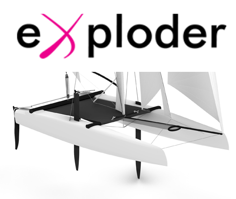
The MayFly is a new A-Class Catamaran design. The boat was designed by Martin Fischer, with important input and help from Jakub Kopylowicz and Woitech Kaliski. The structure of the platform and the foils was designed by Ryszard Partycki. Jakub, Woitech and Ryszard are the people behind the Exploder catamaran range and Martin is known for his F18 designs Capricorn and Wild Cat.
The name of the boat is a tribute to the first successful singled handed flying catamaran named “MayFly”. She was built in the early 70’s and the boat was sailed with great success by Philip Hansford and Ben Wynne in the mid 70’s at Weymouth Speed Week.
Hull Design
Over the last years the hull volume of high performance beach catamarans has significantly increased. Designers found that wider hulls allow pushing the boat harder in stronger winds but don’t slow them down in light conditions. With the design of the MayFly we have of course followed the same direction. The boat has very flat cross sections, little rocker and a very high prismatic coefficient (lots of volume in the extremities of the hull). This provides for good longitudinal stability and reduces pitching, which is always a problem with the extremely light A-Class catamarans.
Today A-Class boats are highly sophisticated designs, and in our opinion it is no longer possible to find a design that is in all conditions faster than the other designs. It is therefore necessary to make a choice in which kind of conditions one wants the boat “to shine”. We made the choice to have a boat that performs very well in medium to strong winds and we were ready to sacrifice slightly the performance in the very light stuff.
We ran numerical simulations of longitudinal stability and hull drag for a number of hull shapes and compared them to two existing A-Class designs. The graphs below show the relative drag difference of the tested hull candidates with respect to a reference hull (existing A-Class). Values below zero indicate lower drag and values above zero indicate higher drag.

Figure 1: Relative hull drag differences for different hull shapes with respect to the reference hull „l_07“ (horizontal line at y=0) as a function of boat speed in knots.
The simulations were made for a total displacement of 150 kg while the boat is sailing on one hull. The horizontal line “l_07” at 0.00% represents the reference hull and the blue line “ref_02” represents a second existing A-Class hull that was taken as a second reference. All the new hull candidates were designed to have the same longitudinal stability (resistance against pitch poling), which is significantly higher than the longitudinal stability of the two reference designs. The figure shows that all the candidates that were tested have significantly more drag at boat speeds from 0 to 5 knots. From 5 knots onwards, however, the new hull shape creates between 1% and 1.5% less drag than the reference hull “l_07”. With respect to the reference hull “ref_02” the crossing is also at 5 knots of boat speed, but the advantage at higher speed is significantly bigger. An A-Class catamaran achieves a boat speed of 5 knots in about 3 to 4 knots true wind speed (TWS). Thus according to the results shown above our new hull shape should be very competitive from 3 to 4 knots TWS onwards.
As most of the current A-Class designs the Mayfly is equipped with curved daggerboards. But in contrast to most other designs the boat uses also lifting surfaces at the rudders. Thus the boat is gradually pushed up if boat speed increases which reduces the hull drag. The lifting rudders provide additional lift, they reduce pitching and they increase the longitudinal stability, compared to a conventional A-Class design. According to our simulations the foils and rudders create about 60 kg vertical lift while sailing upwind in about 10 knots of wind. We therefore tested all hull candidates not only for 150 kg displacement, but also for 90 kg displacement:

Figure 2: As figure 1 but for 90 kg total displacement
The cross over with respect to “l_07” is shifted to slightly lower boat speeds – about 4 knots – and with respect to “ref_02” it is even at 3 knots. Furthermore the drag gain at higher speeds is even larger than for 150 kg displacement.
From these results we are confident that our boat will perform well from 5 knots of true wind speed onwards. In the very light stuff the boat might struggle at bit, but this can probably be compensated with slightly fuller sails.
Foils
It was already mentioned in the previous section that the boat is equipped with curved foils and with lifting rudders. We won’t go into details on the foil and rudder design, just a few hints: The radius of the foils is not constant and they are twisted. The size of the foils and the rudders was set such that they provide a stable configuration for pitch and sinkage variations. Such a configuration enables stable flight in stronger winds, without the need fors a mechanical surface sensor as used on the Moth. We have filed a patent for this type of configuration.
Platform set-up
The platform set-up was entirely developed by Jakub Kopylowicz. The boat features curved cross beams that are glued into the hulls. Thus the deck is completely free of any obstacle. Water passes much easier over the deck and the helmsman can sit anywhere much more comfortably, which is an advantage on downwind courses in very strong winds. The curved beams were designed (shape and structure) by Ryszard Partycki. Furthermore he was in charge of the structure of the hulls and the appendages.
 The deck layout is very clean, and the Harken traveller rail is integrated into the deck. Cunningham, mast rotation and daggerboard control can be adjusted from the trapeze.
Figure 3: Platform lay-out of the Mayfly
Construction
The hulls are entirely built in carbon epoxy with a foam sandwich. The whole hull layup is made with unidirectional tissues. The outer and the inner skin of the hull are made of two layers of UD tissues, oriented at varying angles with respect to the longitudinal axis of the hulls. This provides for better longitudinal and torsional stiffness than hulls built from woven fabrics or biaxial fabrics.
We considered building the hulls with a honeycomb sandwich but refrained from it since it is difficult – and expensive in terms of weight – to ensure water tightness of the very thin outer and inner skin of the hulls. Using Nomex honeycomb instead of PVC foam saves about 1kg per hull. However, in order to be sure that water cannot penetrate into the honeycomb core it is necessary to seal the inner skin and to put additional paint onto the outer skin. Thus the total weight of a honeycomb A-Class hull is more or less the same as for a foam hull, with about the same stiffness. But a foam sandwich is more robust than a honeycomb construction which led us to the decision to use foam.
The hulls are built with 7 bulkheads and for superior longitudinal stiffness we used high modulus UD carbon layers.
The curved beams are a sandwich composite construction without dolphin striker.
Rig
The boat comes with a Fiberfoam carbon mast and with Landenberger sails. It is of course possible to choose a different mast or sail.
 We are also working on a wing mast that represents about 30% of the total sail area. First tests have been made but it is too early to draw any conclusions.
Martin Fischer, martin.ncl (at) gmail.com
Jakub Kopylowicz, j_kopylowicz (at) wp.pl
www.exploder.info
——– Catsailingnews.com


Looks like a weapon!
Great info from Martin. In the pictures i have the sense that the boards are short and highly curved to fit within the a-class rules. I'll be very curious to see what the rudders and boards fully look like.
Is there a website to find out more about the mayfly, its pricing, etc?
Hi, you can get more info on the MayFly either on the Exploder website http://www.exploder.info or directly from Jakub (his e-mail adress is at the end of the article published by Martin) or from Woitech ([email protected]) or from me (also published at the end of the article).
cheers Martin
Looks fantastic – it's great to see real development instead of just refinement.
I wonder how much the A-class rules restricting the curvature of the foils has impacted on the design. Martin: if you had a blank sheet of paper would you still have the same boat?
Hi Fireball, the A-Class rules have in deed big impact on the shape of the foils. Curvature and size are very much restricted. Without these restrictions it would be possible to make the boat dynamically more stable and hence easier to sail. I reckon this would be an advantage for the class, but unfortunately the rules in their current form block this path.
cheers Martin